Sockets - Server & Client 3 - 2020
Continued from Socket - Server & Client 2
Using non-blocking I/O means that we have to poll sockets to see if there is data to be read from them. Polling should usually be avoided since it uses more CPU time than other techniques.
Using SIGIO allows our application to do what it does and have the operating system tell it (with a signal) that there is data waiting for it on a socket. The only drawback to this solution is that it can be confusing, and if we're dealing with multiple sockets we will have to do a select() anyway to find out which one(s) is ready to be read.
#include <sys/time.h>
#include <sys/types.h>
#include <unistd.h>

int select(int numfds, fd_set *readfds, fd_set *writefds,
           fd_set *exceptfds, struct timeval *timeout);
The function monitors sets of file descriptors; in particular readfds, writefds, and exceptfds. If we want to see if we can read from standard input and some socket descriptor, sockfd, just add the file descriptors 0 and sockfd to the set readfds. The parameter numfds should be set to the values of the highest file descriptor plus one. In this example, it should be set to sockfd+1, since it is assuredly higher than standard input (0).
When select() returns, readfds will be modified to reflect which of the file descriptors you selected which is ready for reading.
Using select() is great if our application has to accept data from more than one socket at a time since it will block until any one of a number of sockets is ready with data. In other words, select() gives us the power to monitor several sockets at the same time. It'll tell us which ones are ready for reading, which are ready for writing, and which sockets have raised exceptions, if we really want to know that.
One other advantage to select() is that we can set a time-out value after which control will be returned to us whether any of the sockets have data for us or not.
The select(), though very portable, is one of the slowest methods for monitoring sockets. One possible alternative is libevent that encapsulates all the system-dependent stuff involved with getting socket notifications.
- Active FTP
- FTP server's port 21 from anywhere (Client initiates connection)
- FTP server's port 21 to ports > 1023 (Server responds to client's control port)
- FTP server's port 20 to ports > 1023 (Server initiates data connection to client's data port)
- FTP server's port 20 from ports > 1023 (Client sends ACKs to server's data port)
(*)The main problem with active mode FTP actually falls on the client side. The FTP client doesn't make the actual connection to the data port of the server--it simply tells the server what port it is listening on and the server connects back to the specified port on the client. From the client side firewall this appears to be an outside system initiating a connection to an internal client--something that is usually blocked.
- Passive FTP
- FTP server's port 21 from anywhere (Client initiates connection)
- FTP server's port 21 to ports > 1023 (Server responds to client's control port)
- FTP server's ports > 1023 from anywhere (Client initiates data connection to random port specified by server)
- FTP server's ports > 1023 to remote ports > 1023 (Server sends ACKs (and data) to client's data port)
Visit VPN.
- Hub can't identify the source or intended destination of the information it receives, so it sends the information to all of the computers connected to it, including the one that sent it. A hub can send or receive information, but it can't do both at the same time. This makes hubs slower than switches. Hubs are the least complex and the least expensive of these devices.
- Switches work the same way as hubs, but they can identify the intended destination of the information that they receive, so they send that information to only the computers that are supposed to receive it. Switches can send and receive information at the same time, so they can send information faster than hubs can.
- Routers enable computers to communicate and they can pass information between two networks
- Switches usually work at Layer 2 (Data or Datalink) of the OSI Reference Model, using MAC addresses
- Routers work at Layer 3 (Network) with Layer 3 addresses (IP).
- The algorithm that switches use to decide how to forward packets is different from the algorithms used by routers to forward packets.
- One of these differences in the algorithms between switches and routers is how broadcasts are handled.
- On any network, the concept of a broadcast packet is vital to the operability of a network. Whenever a device needs to send out information but doesn't know who it should send it to, it sends out a broadcast. Broadcasts are used any time a device needs to make an announcement to the rest of the network or is unsure of who the recipient of the information should be.
- A hub or a switch will pass along any broadcast packets they receive to all the other segments in the broadcast domain.
- But a router will not. Without the specific address of another device, it will not let the data packet through. This is a good thing for keeping networks separate from each other, but not so good when we want to talk between different parts of the same network. This is where switches come in.
- Switches don't scale to large networks: table for all destinations may blow up and it may broadcast new destinations to the whole world.
- While there are several technologies such as Ethernet, 4G, and wireless, switches don't work across more than one link layer technology.
- Switches do not provide much for traffic control.
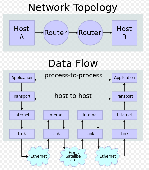
Picture from wiki
Protocols and layering is the primary structuring method used to divide up network functionality. Each protocol instance talks virtually to its peer using the protocol. Also, each instance of a protocol uses only the services of the lower layer.
This is about modularization of a complex system. As we already know the protocol refers to a sequence of communication and computation to control the system. So a modularize the protocol is what people call the layer protocol stack.
This is not for efficiency but for evolvability. In other words, this allows specialization of business sectors, and a common interface among them but also for technology reasons. We have so many unforeseen and unforeseeable needs in the future for our technology that we would rather keep a stack where we can pull out one part of the whole system without having to redesign the entire system.
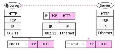
Encapsulation is the mechanism used for protocol layering. So, the lower layer wraps higher layer content, adding its own control information (header/trailer), compression/encryption, segmentation/disassemble, etc. to make a new message for delivery.
Advantages of the network layers abstraction (encapsulation):
- Break a complex task of communication into smaller pieces.
- Lower layers can change implementation without affecting upper layers as long as the interface between layers remains the same. For example, the difference in the underlying connection systems (between wire and wireless) does not affect the upper layer communications as shown in the picture below:
- Lower layers hide the implementation details from higher layers.
| Layer | Unit of Data |
|---|---|
| Application | Message |
| Transport | Segment |
| Network | Packet |
| Link | Frame |
| Physical | Bit |
Summary of IP Network Layer
- The Internet protocol (IP) is an example of a network layer, and is required for all communications in the Internet.
- There are currently two main versions of the IP protocol used in the Internet: IP Version 4, and IP Version 6.
- The Internet protocol is responsible for delivering self-contained datagrams from a source host to the specified destination.
- It makes no promise to deliver packets in order, or at all.
- It has a feature to prevent packets looping forever (TTL).
- It will fragment packets if they are too long.
- It uses a checksum to reduce chances of delivering to wrong address.
| Property | Behavior |
|---|---|
| Data | individually routed packets. Hop-by-hop routing. |
| Unreliable | Packet might be dropped |
| Best effort | if necessary |
| Connectionless | No per-flow state Packets may not be in order |
(*note) An Internet router is allowed to drop packets when it has insufficient resources(best effort service). There can also be cases when resources are available (e.g., link capacity) but the router drops the packet anyways. The following are examples of scenarios where a router drops a packet even when it has sufficient resources:
- A router configured as a firewall, that dictates which packets should be denied.
- An ISP that limits bandwidth consumed by customers, even though there is available capacity.
- TCP is responsible for providing reliable, in-sequence end-to-end delivery of data between applications. In other words, TCP delivers a stream of bytes from one end to the other, reliably and in-sequence, on behalf of an application.
- When a TCP packet arrives at the destination, the data portion is delivered to the service (or application) identified by the destination port number.
- TCP will retransmit missing data even if the application can not use it - for example, in Internet telephony a late arriving retransmission may arrive too late to be useful.
- TCP saves an application from having to implement its own mechanisms to retransmit missing data, or resequence arriving data.
| Property | Behavior |
|---|---|
| Connection oriented | Three-way handshake for connection setup. |
| Reliable | Acknowledgments indicate delivery. Checksums detect corrupted data. Sequence numbers detec missing data. Flow-control prevents overrunning receiver. |
| In-sequence | Data delivered to application in sequence transmitted. |
| Congestion Control | It controls network congestion |

Making Network layer work.
- Internet Protocol (IP)
- creat IP datagrams
- deliver datagrams from end to end hop-by-hop
- Routing Tables - algorithms to populate router forwarding tables
- ICMP
- Examples: ping, tracerouter
- communicates network layer information between end hosts and routers
- reports error conditions
- helps to diagnose problems
| Property | Behavior |
|---|---|
| Reporting Message | Self-contained message reporting error |
| Unreliable | Simple datagram service - no retries |
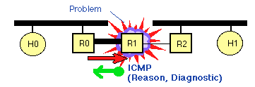
Picture from Internet Control Message Protocol (ICMP)
ping
- ping can be used to measure end-to-end delay.
- ping can be used to test if a machine is alive.
- ping can be maliciously used as a way to attack a machine by flooding it with ping requests.
- ping sends out ICMP ECHO_REQUEST message to the destination.
traceroute
It contains a client interface to ICMP. Like the ping, it may be used by a user to verify an end-to-end Internet Path is operational, but also provides information on each of the Intermediate Systems (i.e. IP routers) to be found along the IP Path from the sender to the receiver. traceroute uses ICMP echo messages. These are addressed to the target IP address. The sender manipulates the TTL (hop count) value at the IP layer to force each hop in turn to return an error message.
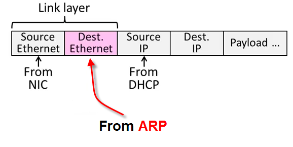
We can retrieve MAC address (Ethernet address) via the Address Resolution Protocol (ARP).
- A network device (e.g. laptop) sends an ARP request to the switch ("I want the MAC address of the device with IP address 192.168.102.3").
- The switch broadcasts the ARP request to all devices.
- The device with the appropriate IP address makes an ARP response back to the switch.
- The switch relays the ARP response back to the network device.
This is in a sense reverse of the DHCP where obtaining IP by giving device info. ARP provides IP info to get device info (MAC address).
Sending bits via network is not perfect, and some bits may be received in error whether due to loss or due to a noise in the signal. How do we detect the error in bits?
Here we will discuss three ways of detecting it:
- Parity
- Checksums
- CRC (Cyclic Redundancy Check)s
Note that those are limited to error detection but not the correction as done in Hamming code etc.
This is the simplest.
We take n data bits, add 1 check bit that is modulo 2 for the sum of the D bits.
For example, let's take 7 bit data: 1001100.
The sum of the bit is 3, then if we do modulo, 3 % 2 = 1
So, the parity bit becomes 1.
The bits we're sending is now 10011001
Note that we used one of the two variants: even parity bit.
We could have used the odd parity bit as shown in the table below.
| 7 bit data | # of 1 bits | Even parity | Odd parity |
|---|---|---|---|
| 0000000 | 0 | 00000000 | 00000001 |
| 10100010 | 3 | 10100011 | 10100010 |
| 1101001 | 4 | 11010010 | 11010011 |
| 1111111 | 7 | 11111111 | 11111110 |
Here is scenario for the successful transmission for even parity assuming we are sending a simple 7-bit value 1001100 with the parity bit (8th bit) following on the right, and with ^ denoting an XOR gate:
- A wants to transmit: 1001100
- A computes parity bit value: 1^0^0^1^1^0^0 = 1
- A adds parity bit and sends: 10011001
- B receives: 10011001
- B computes parity: 1^0^0^1^1^0^0^1 = 0
- B reports correct transmission after observing expected even result.
Summary:
- If an odd number of bits (including the parity bit) are transmitted incorrectly, the parity bit will be incorrect, thus indicating that a parity error occurred in the transmission.
- The parity bit is only suitable for detecting errors; it cannot correct any errors, as there is no way to determine which particular bit is corrupted. The data must be discarded entirely, and re-transmitted from scratch.
- On a noisy transmission medium, successful transmission can therefore take a long time, or even never occur. However, parity has the advantage that it uses only a single bit and requires only a number of XOR gates to generate.
- Parity bit checking is used occasionally for transmitting ASCII characters, which have 7 bits, leaving the 8th bit as a parity bit.
Checksums are widely used in TCP/IP/UDP for error detection and provids stronger protection than parity.
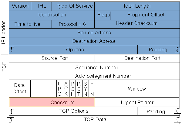
Picture from Cisco: TCP Performance
Here is the description of checksum in RFC793:
The checksum field is the 16 bit one's complement of the one's complement sum of all 16-bit words...
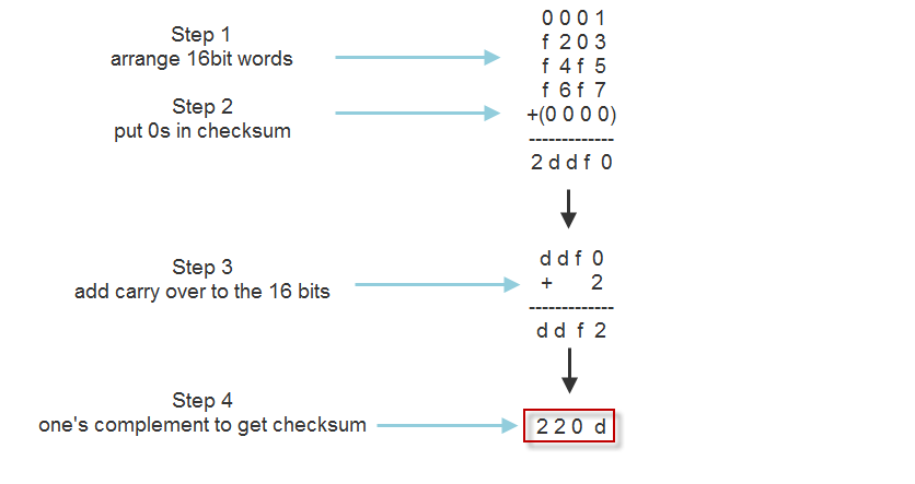
Sending can be divided into 4 steps:
- Arrange data in 16-bit words
- Put zero in checksum position
- Add any carryover back to get 16 bits
- Complement to get sum
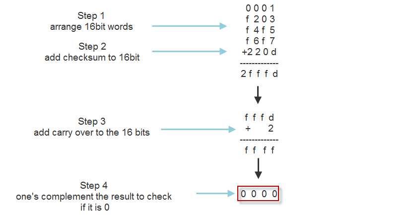
Receiving can also be divided into 4 steps:
- Arrange data in 16-bit words
- Add checksum to the 16-bit words
- Add any carryover back to get 16 bits
- Complement the result and check if it is 0
CRCs are so called because the check (data verification) value is a redundancy (it expands the message without adding information) and the algorithm is based on cyclic codes. - wiki
Given n data bits, generate k check bits such that the n+k bits are evenly divisible by a divisor D.
For example, n=301, k=1, and D=3:
the bits to send would be 4 bits: 301?. But we can start with 3010. 3010 % 3 = 1, so to make it divisible by D=3, it should be 3012.
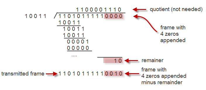
Sending procedure should be like this:
- Extend the n data bits with k zeros.
- Divide by the divisor D.
- Keep remainder, and throw away quotient.
- Adjust k check bits by remainder.
This picture below is for the case when
- Data bits: 1101011111
- Check bits, k = 4
- Divisior, D = 10011
Receiving procedure is the same, and need to check if the remainder is zero.
Dominant model for network applications is TCP Byte Stream model where one side writes and the other side reads. It's the building block of most applications today though ther models are there such as datagrams, real-time streams.
- web server http
- skype client
Rendezvous service that allows users not behind a NAT to call users behind a NAT.
An Analysis of the Skype Peer-to-Peer Internet Telephony Protocol by Salman A. Baset and Henning Schulzrinne(pdf) - Bit Torrents
Tit For Tat algorithm - gives download preference to peers that give data to you.
Visit P2P
https://wiki.theory.org/BitTorrentSpecification
Beej's Guide to Network Programming
Using Internet Sockets
or get it from http://beej.us/guide/bgnet/output/print/bgnet_USLetter.pdf
Ph.D. / Golden Gate Ave, San Francisco / Seoul National Univ / Carnegie Mellon / UC Berkeley / DevOps / Deep Learning / Visualization