Spatial Data Structure & Physics Engine
Note: This chapter is very simple and shallow introduction to games in general. I'll try to put more informative materials in the near future.
A spatial data structure is one that organized geometry in two- and three- dimensional hierarchical structures. So, the structure is nested and of recursive nature.
Commonly used types of spatial data structures are:
- Bounding Volume Hierarchies (BVHs)
- Binary Space Partitioning (BSP) trees
- Quadtrees
- Octrees
BSP trees and octrees are data structures based on space subdivision. In other words, the entire space of the scene is subdivided in the data structure. For instance, the union of the space of all the leaf nodes is equal to the entire scene. Most variants of BSP trees are irregular (the space can be subdivided more arbitrarily) while octree is regular. On the other hand, BVH is not a space subdivision structure but it encloses the regions of the space surrounding geometrical objects.
Bounding volume (BV) is a volume enclosing a set of objects. It is much more simpler in terms of geometry than the objects inside. So, performing tests using BV is faster than using objects enclosed. Examples of BVs are:
- Spheres
- Axis-aligned bounding boxes (AABBs)
- Oriented bounding boxes (OBBs)
- Discrete oriented polytope (k-DOP)
Though BV does not involved in rendering images, it is used as a proxy in place of the bounded objects, to speed up rendering, selection, and other computations and queries.
In the picture below, the left drawing shows a simple scene with six objects, each enclosed by a bounding sphere. The bounding spheres are then grouped together into larger bounding spheres, until all objects are enclosed by the largest sphere. The right diagram demonstrates the bounding volume tree hierarchy that is used to represent the object hierarchy on the left side picture. The BV encloses all objects in the scene.
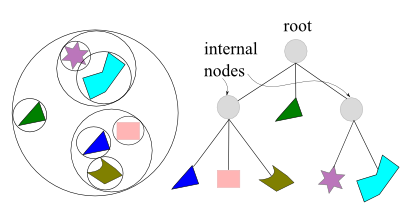
For real-time rendering of 3-dimensional scenes, the BVH is often used for hierarchical view frustum culling. The scene is organized in a hierarchical tree structure, consisting of a root, internal nodes, and leaves. A leaf node holds the actual geometry to be rendered, and it does not have any children while an internal node has pointers to its children.
k-ary or k-way tree is a rooted tree in which each node has no more than k children. A higher k gives a tree with a lower height, which means that it takes fewer steps to traverse the tree, but it requires more work at each node.
BVH are also excellent for performing various queries: ray tracing, getting closes distance, and for dynamic scenes.
To create a BVH, we need to be able to compute a tight BV around a set of objects and then, actual hierarchy of BVs must be created.
Binary space partitioning (BSP) trees exist as two noticeably different variants in computer graphics, which we call axis-aligned and polygon-aligned.
The trees are created by using a plane to divide the space in two, and then sorting the geometry into these two spaces. This process is done recursively. One aspect of these trees is that if the trees are traversed in a certain way, the geometrical contents of the tree can be sorted front-to-back from any point view. This sorting is approximate for axis-aligned and exact for polygon-aligned BSPs. On the other hand, the BVHs usually do not include any type of sorting.
- Axis-Aligned BSP Tree
The creation of an axis-aligned BSP tree is done as follows. First, the whole scene is enclosed in an axis-aligned bounding box (AABB). Then, subdivide that box into smaller boxed recursively. Suppose, there is a box at any recursion level. One axis of the box is chosen, and a perpendicular plane is generated that divides the space into two boxes.
As object intersecting the plane can be treated in any number of ways. For instance, it could be stored at this level of the tree, or made a member of both child boxes, or split by the plane into two separate objects.
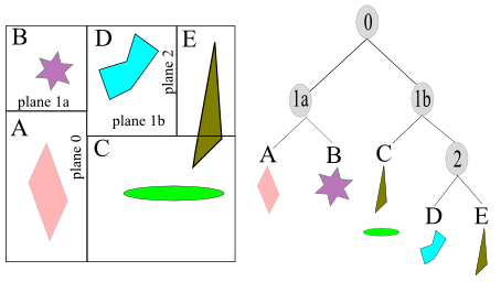
The picture above shows axis-aligned BSP tree. The space partitions are allowed to be anywhere along the axis, not just at its midpoint. The spatial volumes formed are labeled A through E. The tree on the right side demonstrates the underlying BSP data structure. Each leaf node represents an area, with that area's content shown beneath it. Note that overlapped triangle showed up in C and E.
- Polygon-Aligned BSP Tree
The other type of BSP is the polygon-aligned form. This data structure is particularly useful for rendering static or rigid geometry in an exact sorted order. This algorithm was popular when there was no hardware Z-buffer, and still has occasional use such as collision detection.
The octree is similar to the axis-aligned BSP tree. A box is split simultaneously along all tree axes, and the split point must be the center of the box. This creates eight new boxes. The makes the structure regular. In two-dimensional case, it becomes quadtree as shown in the picture below.

Octrees can be used in the same way as axis-aligned BSP trees, and thus, can be handle the same types of queries. Actually, BSP tree can give the same partitioning of space as an octree. If a cell is first split along the middle of the x-axis, then the two children are split along the middle of y-axis, and finally those children are split in the middle along z-axis, eight equal-sized cells are formed that are the same as those created by one application of an octree division.
One source of efficiency for the octree is that it does not need to store information needed by more flexible BSP tree structure. For instance, the splitting plane locations are known and so do not have to be described explicitly. This more compact storage scheme also saves time by assessing fewer memory locations during traversal. Axis-aligned BSP can still be more efficient, as the additional memory cost and traversal time due to the need for retrieving the splitting plane's location can be outweighed by the savings from better plane placement. There is no overall best efficiency scheme; it depends on the nature of the underlying geometry, the use pattern of how the structure is accessed, and the architecture of the hardware running the code, and so on.
BVH, BSP trees, and octrees all use a sort of tree as their basic data structure. It is in how they partition the space and store the geometry that they differ. They also store geometrical objects, and nothing else, in a hierarchical fashion. However, rendering a three-dimensional scene is not just about geometry. Control of animation, visibility, and other elements are usually performed using a scene graph. This is a user oriented tree structure that is augmented with textures, transforms, levels of detail, render states, light sources, and so on.
It is represented by a tree, and this tree is traversed in depth-first order to render the scene. For example, a light source can be put at an internal node, which affects only the contents of its subtree. Another example is when a material is encountered in the tree. The material can be applied to all the geometry in that node's subtree, or possibly be overridden by a child's settings. In fact, more or less, every graphics application uses some form of scene graph.
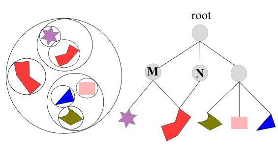
In the picture above, shows a scene graph with different transformation M and N applied to internal nodes, and their respective subtrees. Note that these two internal nodes also point to the same object, but since they have different transformations, two different objects appear. The other one is rotated and scaled.
The articles on physics and collision are based on wiki.
A physics engine is computer software that provides an approximate simulation of certain simple physical systems:
- rigid body dynamics (including collision detection)
- soft body dynamics
- fluid dynamics
- Collision Detection
- Collision detection is a geometric problem
- Given two moving object configuration, determine if they intersected at some point between initial and final states.
- Collision Response
- The response to collisions is the actual physics problem of determining the unknown forces/impulses of the collision.
In most computer games, speed of simulation is more important than accuracy of simulation. This leads to designs for physics engines that produce results in near real-time but that is not necessarily real world physics.
Typically, we represent 3D objects as meshes or shapes. Meshes are usually complex and detailed shape visible to the player in the game while simplified invisible mesh is used to represent the object to the physics engine so that the physics engine treats the complex object as a simple cylinder.
This simplified mesh used for physics processing is often referred to as the collision geometry. This may be a bounding box (AABB (axis aligned bounding box), OBB (oriented bounding box)), sphere, or convex hull. Engines that use bounding boxes or bounding spheres as the final shape for collision detection are considered extremely simple. Generally a bounding box is used for broad phase collision detection to narrow down the number of possible collisions before costly mesh on mesh collision detection is done in the narrow phase of collision detection.
In this system, a 3-dimensional, volumetric tessellation is used to create 3D objects and the tessellation results in a number of finite elements which represent aspects of the object's physical properties such as toughness, plasticity, and volume preservation.
Once constructed, the finite elements are used by a solver to model the stress within the 3D object. The stress can be used to drive fracture, deformation and other physical effects with a high degree of realism and uniqueness. As the number of modeled elements is increased, the engine's ability to model physical behavior increases.
The visual representation of the 3D object is altered by the finite element system through the use of a deformation shader run on the CPU or GPU.
Though the Finite Element-based systems had been impractical for use in games due to the performance overhead and the lack of tools to create finite element representations out of 3D art objects, with the increase of computing power, volumetric tessellations, real-time finite element systems began to be used in games.
Physics-based character animation in the past only used rigid body dynamics because they are faster and easier to calculate, but modern games and movies are starting to use soft body physics. Soft body physics are also used for particle effects, liquids and cloth. Some form of limited fluid dynamics simulation is sometimes provided to simulate water and other liquids as well as the flow of fire and explosions through the air.
- Penalty methods, where interactions are commonly modeled as mass-spring systems. This type of engine is popular for deformable, or soft-body physics.
- Constraint based methods, where constraint equations are solved that estimate physical laws.
- Impulse based methods, where impulses are applied to object interactions.
Game physics involves the laws of physics into a game engine for the purpose of making the effects appear more real to the observer.
A common aspect of computer games that model some type of conflict is the explosion. The effects of the explosion can be modeled as the split and shattered components propelled by the expanding gas. This is modeled by means of a particle system simulation. A particle system model allows a variety of other physical phenomena to be simulated, including smoke, moving water, precipitation, and so forth.
This is a technique to display the movement of a character when killed. It treats the character's body as a series of rigid bones connected together with hinges at the joints. The simulation models what happens to the body as it collapses to the ground.
More sophisticated physics models of creature movement and collision interactions require greater level of computing power and a more accurate simulation of solids, liquids, and hydrodynamics. The modeled articulated systems can then reproduce the effects of skeleton, muscles, tendons, and other physiological components.
Rendering pipeline construction can be divided as three stages: Application stage, Geometry stage, and Raster stage.
This is generally implemented in software running on CPUs. The tasks are collision detection, a response from the detection, global acceleration algorithms such as hierarchical view frustum culling, and animations (texture animation or animation via transformation), physics simulation, and so on. At the end of this application stage, the geometry to be rendered (rendering primitives) is fed to the geometry stage.
Transforms and projections are done at this stage. So, this stage computes what is to be drawn, how it should be drawn, and where it should be drawn. This stage is typically performed on GPUs that contains programmable cores as well as fixed-operation hardware.
This geometry stage is responsible for the majority of the per-polygon and per-vertex operations. This stage can be divided into the following functional stages:
- Model and view transform
model coordinates -> (Model Transformation) -> world coordinates -> (View Transformation) -> eye coordinates - Vertex shading: Calculation of the effect of lights on materials.
- Projection: Transforming (orthographic/perspective) the view volume into a unit cube so that the models are in normalized device coordinates.
- Clipping: Only the objects which are inside the view volume will be passed on to the next stage, which is rasterizer stage. Sectioning could be done here.
- Screen Mapping
eye coordinates -> screen coordinates (x, y) and depth (z) -> window coordinates
This stage renders (draws) an image with the data generated from the previous stage as well as any per-pixel computation. The data at the start of this stage has been transformed and projected with their associated shading information. What the rasterizer stage is doing is to compute and set colors for the pixels of the object. This stage is processed completely on the GPU. Z-buffer, stencil buffer, and frame buffers are for this stage.
After all the primitives passed to this rasterizing stage, objects visible from the point of camera view are displayed on screen. The screen displays the contents of the color buffer, which are usually rendered into back buffer and then swapped with the contents of the front buffer.
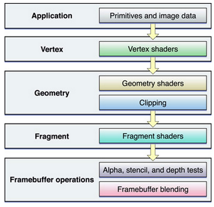
Picture from OpenGL Shader Pipeline
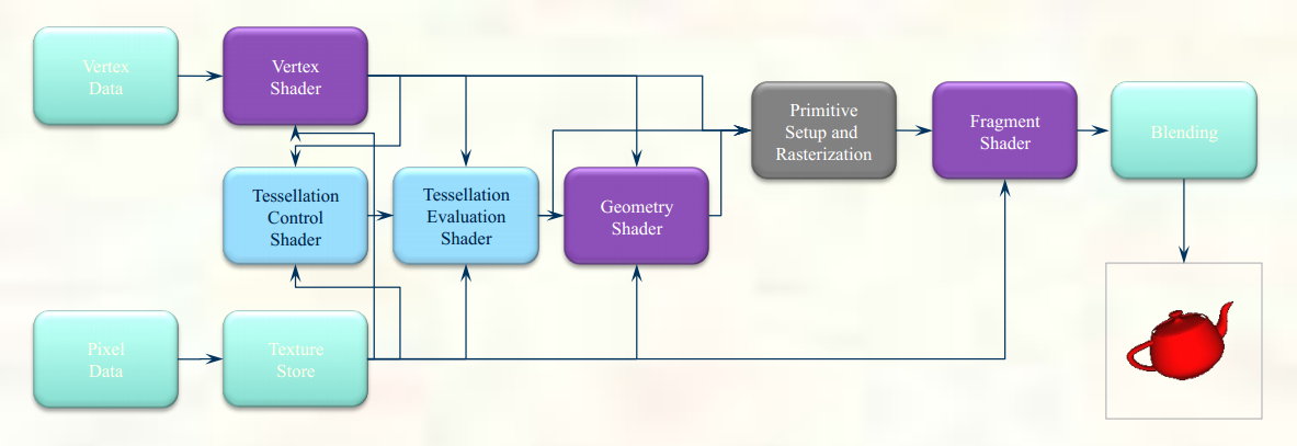
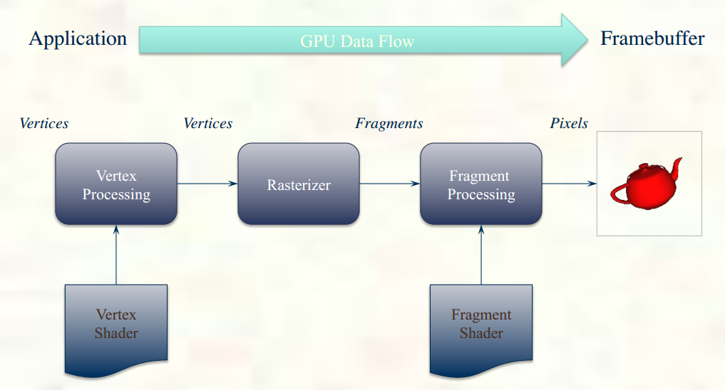
Pictures from Introduction to Modern OpenGL Programming
- Vertex shader
The purpose of this stage is to transform each vertex's 3D position in virtual space to the 2D coordinate. In other words, the vertex shader calculates the projected position of the vertex in screen space. The vertex shader can also generate other varying outputs, such as a color or texture coordinates, for the rasterizer to blend across the surface of the triangles connecting the vertex. - Geometry shader
Geometry shaders are a relatively new type of shader, introduced in OpenGL 3.2. It can generate new graphics primitives, such as points, lines, and triangles, from those primitives from beginning of the graphics pipeline. Geometry shader programs are executed after vertex shaders. The primitives from the geometry shader are rasterized and their fragments ultimately passed to a pixel shader. - Pixel (Fragment) shader
The generated fragments from rasterizer stage then pass through this fragment shader. The fragment shader receives the varying values output by the vertex shader and interpolated by the rasterizer as inputs. It outputs color and depth values that then get drawn into the framebuffer. Common fragment shader operations include texture mapping and lighting. Since the fragment shader runs independently for every pixel drawn, it can perform the most sophisticated special effects. However, it is the most performance-sensitive part of the graphics pipeline.
For more on OpenGL, please visit Visualization.
Ph.D. / Golden Gate Ave, San Francisco / Seoul National Univ / Carnegie Mellon / UC Berkeley / DevOps / Deep Learning / Visualization